Stormwater Management Technologies: Flow Control Devices
Following a contamination of infrastructure, state and local agencies may need to implement control measures to contain or redirect stormwater. EPA is developing and testing technologies to support stormwater management.
Go back to the Stormwater Management Implementation Control Technologies page.
Flow Control Devices

Controlling water flow to streams is important to prevent flooding, control erosion, and improve aquatic habitat. Aquatic habitats are negatively impacted when streams go through intermittent dry periods or the stream bed is scoured during high flow periods. There are many components to maintaining healthy stream environments such as maintaining a robust riparian zone, and controlling nutrient runoff, but physical flow control devices are components of the overall toolbox for stream management.
Detention and retention basins are stormwater management structures that collect runoff and reduced flow to surface water bodies to decrease the risk of flooding and erosion.
The difference between a detention basin and a retention basin, is the presence or absence of a permanent pool of water, or pond. The water level in both types of basins is controlled outflow orifice. A detention basin has this orifice at the bottom of the basin and does not have a permanent pool of water. All the water runs out, at a controlled rate, between storms and the basin is usually dry. A retention basin has an orifice at a higher point and therefore retains a permanent pool of water. Water is released during storm events when the water level in the basin reaches the level of the orifice. A retention pond retains water between storm events, thus looks like a natural pond, but plays an important role in controlling stormwater runoff.
Detention and retention basins are frequently used as a stormwater runoff best management practice to provide general flood protection, lessen extreme floods, and improve water quality (if equipped with treatment devices). EPA is building models to optimize utilization of existing basins in response to a spill or release of contaminant.
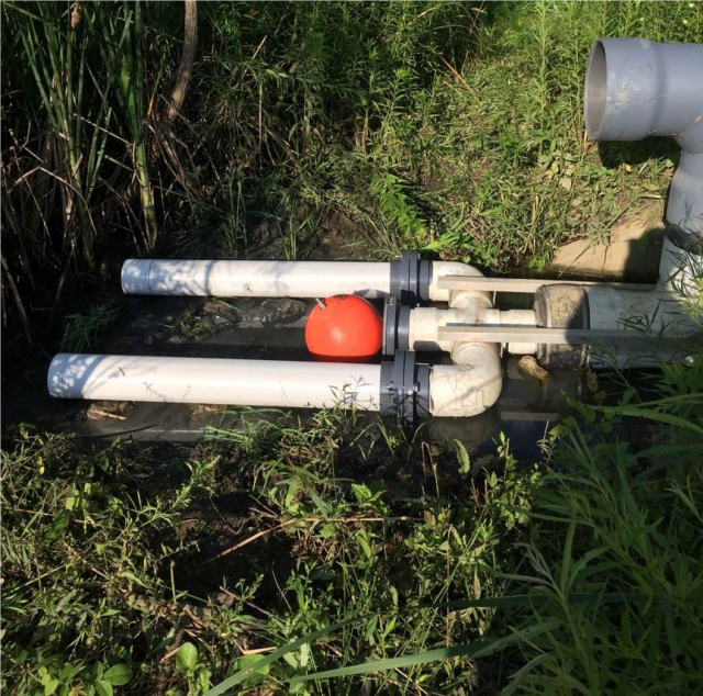
The EPA designed and tested the Detain H2O Retrofit Device to improve the performance of existing detention basins by reducing erosive flows in receiving channels and improving water quality (see related article on treatment media). The low-cost technology prolongs storage times in the basins by restricting the discharge below the critical threshold for erosion in the receiving stream (Qcritical). The device can abate downstream bank erosion and total suspended solids loads, enhance channel stability and aquatic habitat, and restore biota. Low to medium storm events (~<2-yr occurrence) will pass through the throttled retrofit device and optional filter media and be released to reduce channel erosion. A portion of larger flows (such as the 100-yr recurrence) can be routed through the bypass to provide similar performance to the original flood control detention basin design.
Another option for stormwater flow control was theoretically evaluated by the Hamilton County, Ohio Soil and Water Conservation District with technical support from the EPA. This option would retrofit sewer outfalls (man-made pipes, culverts, channels, etc. where stormwater is discharged to receiving water bodies) to control the rate of flow and quality of the water discharged from the sewer system. As with the detention basin retrofit device, the goal of the sewer retrofit devices is to restrict the discharge to below the critical threshold for erosion in the receiving stream while allowing enough flow to avoid flooding upstream.
Two types of retrofit devices were considered. A flap gate retrofit consists of a flap gate, with a low flow opening and a mechanism to keep the flap gate closed (pictured below). The device must be engineered with an opening that allows water to pass through at a rate that does not cause downstream erosion and enough force on the flap to keep it closed until the height of the water detained behind the flap rises to the point that could cause upstream flooding. At this critical height the weight of the water behind the flap must be enough to open the flap and allow unrestricted flow.
A riser retrofit consists of a riser installed at the end of a storm sewer outfall. An opening at the bottom of the riser allows water to pass through a rate that would not cause erosion downstream. When water backs up behind the riser to a point at which flooding may occur upstream water would be discharged through an overflow opening at the top of the riser.
Flap gate retrofit devices – would be preferable because they can be designed such that the flap will fully open allowing the sewer pipe to convey water as through there were no retrofit; whereas the riser retrofit will always impede flow to a degree. Riser retrofits are used in situations where enough force cannot be applied to keep a flap gate closed against the weight of the water in the pipe.
EPA developed a spreadsheet calculation/decision support tool to determine if retrofitting a sewer outfall could levelized flow to the receiving stream while not restricting flow as to cause upstream flooding. This tool was used to determine the viability of a retrofit at a sewer outfall to the Upper Cooper Creek in Hamilton County, Ohio. Although results from the decision support tool indicated that these controls would not be appropriate in Cooper Creek, these retrofits may have application at other locations.
EPA and the Hamilton County Soil and Water Conservation District developed a methodology for evaluating sewer outfalls to determine if they can be retrofitted sufficiently to decrease the frequency of erosive discharges while preventing upstream flooding. Links to a users’ manual and excel-based model that can be used to make this evaluation and to provide preliminary design parameters are available in the box to the right of the page.
